
A Novel Deployable Tied Arch Bridge |
|||
|
|||
SUMMARY |
|||
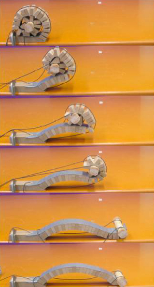
Deployable bridges were first invented in WWI to aid with tank logistics in areas with damaged or inadequate infrastructure. Today, these bridges play a variety of roles in both military and relief operations. The bridges themselves come in many sizes: from 8.5 m (28 ft) ‘man portable’ bridges to 45 m (150 ft) bridges capable of carrying tanks. Despite the number of deployable bridges that have been proposed, almost all have taken on the same structural form: a simply supported beam. This project explores new structural forms, new deployment techniques, and the potential benefits of adding "smart features" to the bridge such as sensors and actuators. The project leader, George Lederman ‘10, a member of the SHM lab, proposes a novel deployable tied arch bridge that includes both a novel deployment sequence and a novel structural form. Figure 1 shows the sequence in which the proposed bridge might be deployed. In his senior thesis “A Novel Deployable Tied Arch Bridge” Lederman demonstrates the feasibility of the design by assessing the performance of a reduced scale physical model equipped with fiber optic strain gauges, a capacitance load cell, and a winch. George Lederman was awarded Civil and Environmental Engineering Book Award for the best Senior Thesis and David W. Carmichael Prize presented in recognition of strong academic work and an outstanding thesis (June 2010). His experience in SHM lab is presented in 2010 edition of "Senior Thesis Quintessentially". |
|
||
THE CONCEPT |
|||
The bridge concept originated from research Lederman performed in Dr. Zhong You’s Lab at Oxford University. The bridge requires only one actuator to deploy (Figure 1) and can retract to a relatively small package size. The structural form of the bridge, a tied arch, allows for greater structural efficiency, and the unrolling deployment sequence, allows for lower stresses during deployment. Fiber optic strain gauges and capacitance load cell allow for monitoring of strain in the arch, control of presstressing force in the cable, and adjustment of force in cable and deformed shape of the arch to external loads. |
|||
BUILDING AND MONITORING THE PHYSICAL MODEL |
|||
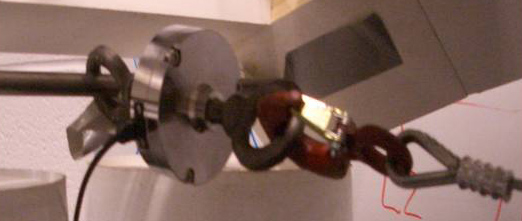
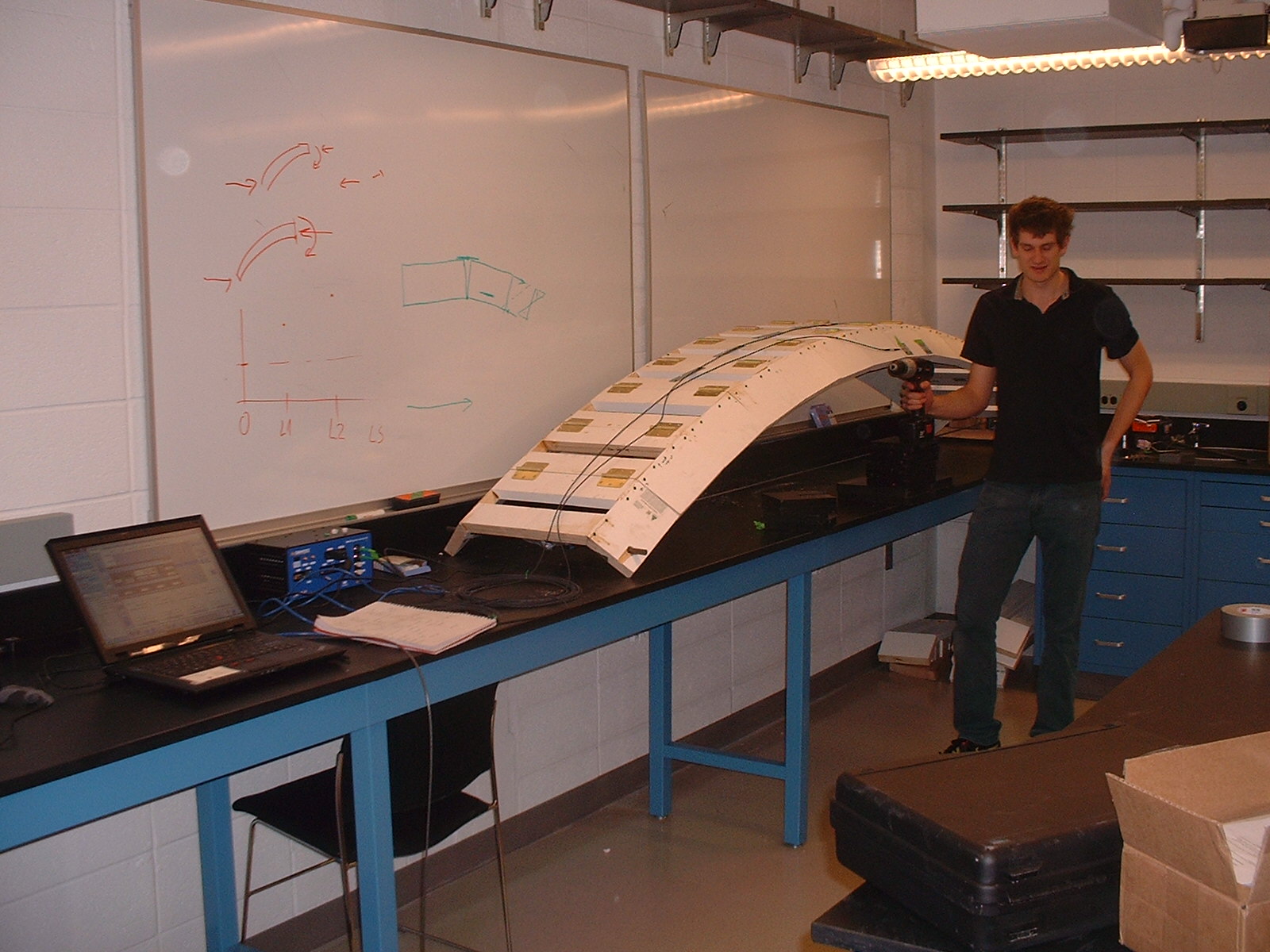
The model was built of wood with 25 cm (10 inch) long sections such that fiber optic sensors could be placed on each segment. Optical fibers with Bragg gratings were transformed into the strain gauges by gluing the fibers to the brackets as shown in Figure 2. The fiber optic sensors (FOS) were calibrated using a stage and micrometer set up. Load cell was added in order to monitor and control the force in the cable (see Figure 3). The physical model of the bridge before testing is shown in Figure 4. |
|||
Fig. 2: Bragg grating fiber optic sensor (FOS).
Fig. 3: Capacitance load cell installed on the cable. |
Fig. 5: Smart deployable tied arch bridge ready for testing. |
||
TESTING THE BRIDGE |
|||
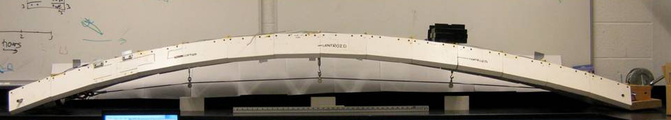
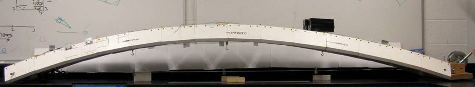
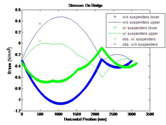
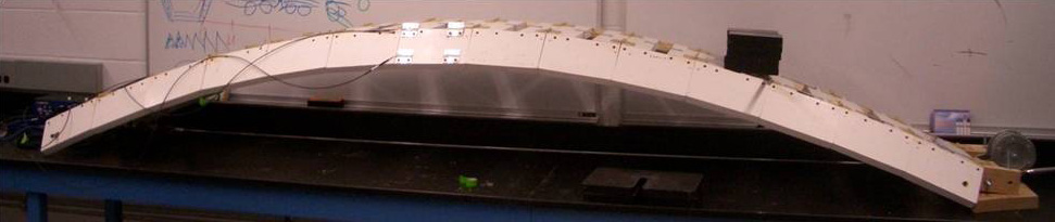
The bridge was tested to compare the predicted stresses with the observed stresses from the FOS. In order to reduce the bending moments in the arch, vertical suspenders which connect the horizontal cable to the arch itself were added. Figure 6 shows the bridge with and without vertical suspenders. Example of comparison between predicted and observed stresses is shown in Figure 7. The thin lines show the stress along the top edge of the bridge, while the thick + lines show the stress along the bottom of the bridge. In addition, the blue lines are the stresses without suspenders and the green lines include the suspenders. |
|||
Fig. 6: Testing the bridge physical model with and without vertical suspenders. |
|
||
CONCLUSIONS |
|||
This project demonstrated the structural efficiency of the bridge and its potential for larger scale application. In addition, it shows the benefits of "smart features" - sensors and actuators - in its adaptability to loading conditions and to a wide range of projects. |
|||
ACKNOWLEDGEMENTS |
|||
This project has been realized with important support, great help, and kind collaboration of several professionals and companies: Lidow Independent Work/Senior Thesis Fund Peter Bogucki, Associate Dean for Undergraduate Affairs, School of Engineering and Applied Science, Princeton University Zhong You, Department of Engineering Science, University of Oxford, UK Joe Vocaturo, Senior Technical Support Staff, Department of Civil and Environmental Engineering, Princeton University Ted Zoli, HNTB Corporation, New York, NY The staff of Department of Civil and Environmental Engineering, Princeton University
|
|||
|
|||